
The Reason
I’ve been hooked on HomeAssistant for a while now, tinkering with all sorts of gadgets—smart plugs, lights, solar inverters, car chargers, you name it. Most of these were a breeze to set up in HomeAssistant. Even the trickier ones, like soldering circuit boards and flashing ESPHome with custom code, weren’t too bad because someone in the community had already paved the way with their code.
Now, I feel it’s my turn to give back. I’ve got a Hayward heat pump for my pool, and it didn’t come with any smart features to hook it up to HomeAssistant. I scoured the web and found out it supports an external display or a Wi-Fi module, which hinted that I could control it remotely. The catch? The Wi-Fi module was tough to track down without breaking the bank.
 My Hayward heat pump
After digging through forums, I struck gold on the Jeedom community. Someone figured out that the heat pump’s touch panel and external modules talk to the control board using Modbus, a communication protocol. They hooked up an ESP8266 microcontroller to the port meant for the Wi-Fi module and wrote code to monitor and control the heat pump. Their work, shared in two GitHub repos (freddye83/esp8266_warmpool and cribskip/esp8266_poolstar), showed it works for Hayward, Silverline, and maybe other brands too. They sniffed the data between the touch panel and the control board, then programmed the ESP8266 to act as a Modbus server, pretending to be a second control interface.
Their success got me pumped. I decided to build my own ESP8266-based controller to get my heat pump talking to HomeAssistant, using ESPHome to keep things smooth and simple.
The Process
Putting together the hardware for my ESP8266-based Modbus interface was pretty straightforward, especially if you’re comfortable with a soldering iron. I’m no expert, but I got it done, and I’m stoked to share how it came together.
Parts I Used
Here’s what I grabbed to make this work, with rough prices from AliExpress:
- Wemos D1 Mini – about 2-3€
- Step-Down DC Power Supply – under 1€
- TTL to RS485 Module – under 1€
- JST Connectors – for making your own cable
- Wires – about 0.5-1m each in four different colors for easy tracking
Wiring It Up
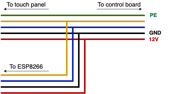
The Hayward heat pump has a 5-pin JST connector linking the touch panel to the control board. It carries Protected Earth (PE), Data+, Data-, Ground, and +12V. I made a Y-cable with the same JST connector to tap into this connection without messing with the original setup. You can probably buy a similar cable if your heat pump came with an optional module.
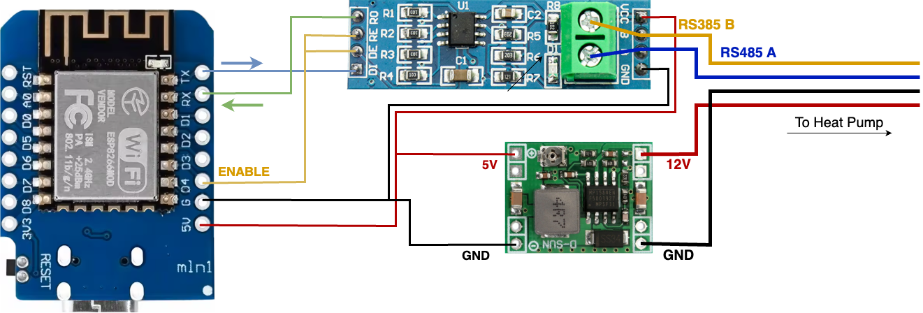
For my setup, I skipped the PE pin and used Ground and +12V to power the board, plus the Data+ and Data- for Modbus communication. The +12V and Ground from the heat pump go to the step-down power supply, which I set to output 5V to power the Wemos D1 Mini and the RS485 module. The Data+ and Data- wires connect to the A and B inputs on the RS485 module. If the touch panel shows connection errors or you don’t see data, try swapping these two wires.
For communication between the ESP8266 and the RS485 module, I used the standard serial interface. Connect the ESP’s TX pin to the RS485’s DI pin, and the ESP’s RX pin to the RO pin. Then, tie the RS485’s DE and RE pins to a single data pin on the ESP—this acts as the flow control pin in the software config.
Here’s a rough schematic of how it all hooks up:
 Y cable connections
 Schematic diagram
As with any other device, disconnect it from mains power before working on it. Making and breaking connections while powered can lead to parts damage and those will be expensive to replace. Touching a live wire while working on it could lead to a painful stop of all your future projects.
Here’s what my setup looks like—not very clean for now, but it works! I’ll get around to putting it in a proper enclosure soon. For now it’s tightly packed and placed inside the heat pump.
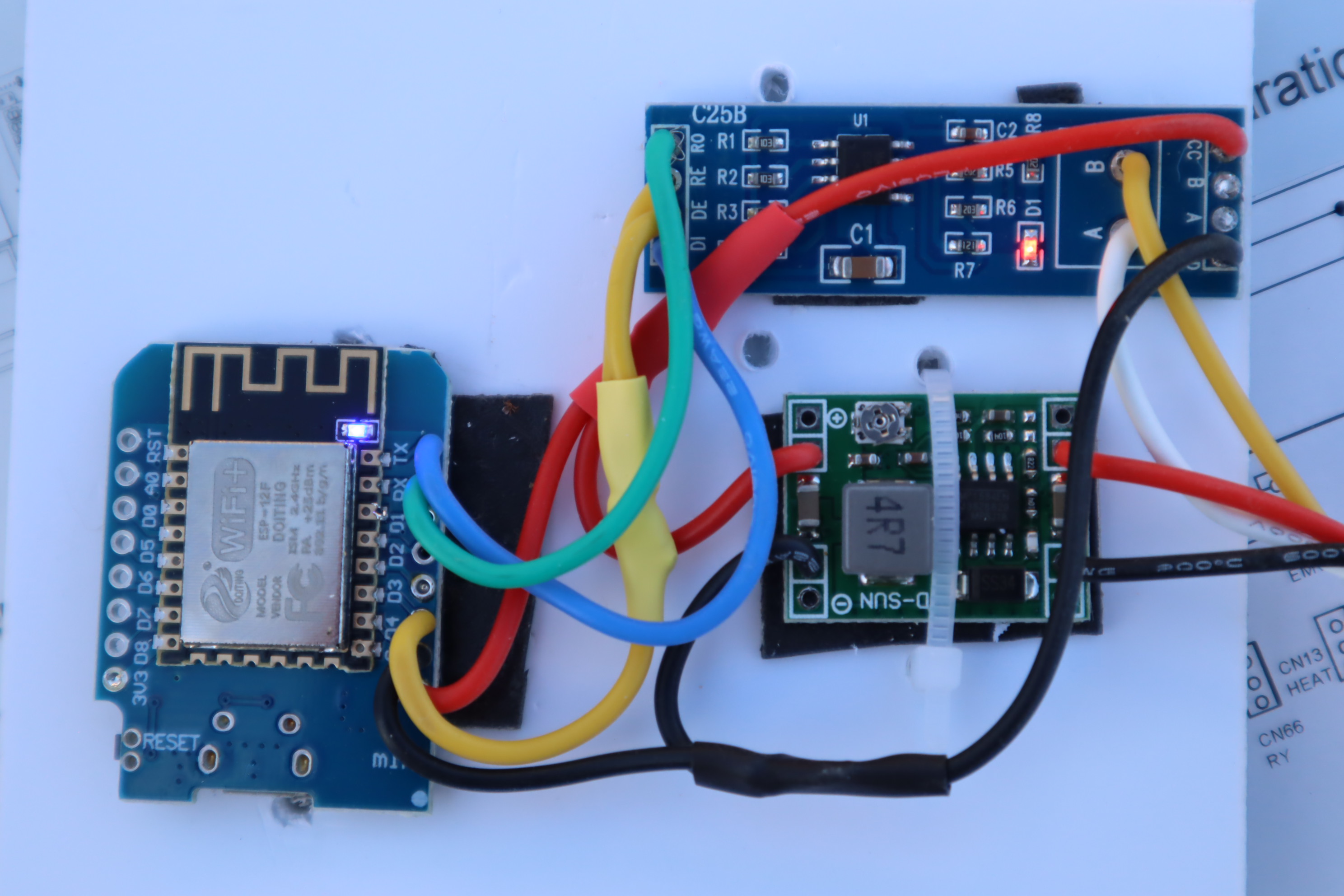 My end result
Digging Through Data
With the hardware hooked up, I was pumped to figure out what the heat pump was saying. My goal was to snoop on the messages flying between the touch panel and the control board to make my ESP8266 play nice with them. The ESPHome Modbus component wasn’t showing me all the traffic on the bus—or maybe I just didn’t know how to make it spill the beans. So, I rolled up my sleeves, grabbed the Modbus Application Protocol Specification V1.1b3 and checked out Modbus Tools for some guidance. Then, I tweaked the ESPHome Modbus component to log every message it saw.
Modbus is a serial communication protocol that enables devices to exchange data in a master-slave configuration. It uses numbered registers to store and transmit information like temperature, on/off status, or configuration settings. Devices communicate by sending requests to read or write these registers. Modbus is commonly used in industrial processes.
After some coding, I could finally see the communication in action. The control board sends a broadcast message (to device 0x00) every second, writing 90 registers starting at address 2001, packed with sensor data. It also sends read requests for 30 registers starting at 3001 to device 0x01 (the touch panel) and device 0x02 (which was silent). That was my “aha!” moment—by pretending to be device 0x02, my ESP8266 could talk to the control board!
Here’s a sample of these messages:
1
2
3
4
5
6
7
8
9
10
11
12
[15:53:01][D][modbus:189]: Device 0x01 Requesting Read Holding Registers(0x03) 30 elements starting at address 3001.
[15:53:01][D][modbus:244]: Device 0x01 Responding Read Holding Registers(0x03) with 60 bytes of data:
[15:53:01][D][modbus:251]:  Values: 22342, 12848, 12338, 12856, 12336, 13622, 0, 0, 257, 3001, 0, 0, 0, 0, 24, 82, 85, 0, 0, 0, 0, 0, 0, 0, 0, 0, 0, 0, 0, 0,
[15:53:01][D][modbus:253]:  Hex: 57.46.32.30.30.32.32.38.30.30.35.36.00.00.00.00.01.01.0B.B9.00.00.00.00.00.00.00.00.00.18.00.52.00.55.00.00.00.00.00.00.00.00.00.00.00.00.00.00.00.00.00.00.00.00.00.00.00.00.00.00 (60)
[15:53:01][D][modbus:189]: Device 0x02 Requesting Read Holding Registers(0x03) 30 elements starting at address 3001.
[15:53:02][D][modbus:205]: Device 0x00 Request Write Multiple Registers(0x10): 90 elements (180 bytes) starting at address 2001.
[15:53:02][D][modbus:207]:   57.46.32.30.30.32.32.38.30.30.35.36.00.00.00.00.01.01.07.D1.00.00.00.01.00.00.00.00.00.00.00.00.00.00.00.00.00.00.00.C8.00.00.00.00.00.E6.00.02.00.00.00.02.00.00.00.00.00.00.00.00.00.00.00.00.00.00.00.00.00.00.00.00.00.00.00.00.00.00.00.00.00.00.00.00.00.00.00.0>
[15:53:02][D][modbus:258]: Device 0x00 Responding Write Multiple Registers(0x10):  Written 90 elements starting at address 2001.
[15:53:02][D][modbus:189]: Device 0x01 Requesting Read Holding Registers(0x03) 30 elements starting at address 3001.
[15:53:02][D][modbus:244]: Device 0x01 Responding Read Holding Registers(0x03) with 60 bytes of data:
[15:53:02][D][modbus:251]:  Values: 22342, 12848, 12338, 12856, 12336, 13622, 0, 0, 257, 3001, 0, 0, 0, 0, 24, 82, 86, 0, 0, 0, 0, 0, 0, 0, 0, 0, 0, 0, 0, 0,
[15:53:02][D][modbus:253]:  Hex: 57.46.32.30.30.32.32.38.30.30.35.36.00.00.00.00.01.01.0B.B9.00.00.00.00.00.00.00.00.00.18.00.52.00.56.00.00.00.00.00.00.00.00.00.00.00.00.00.00.00.00.00.00.00.00.00.00.00.00.00.00 (60)
How the Communication Works
Thanks to the Jeedom community, I didn’t have to start from scratch. They’d already mapped out the key registers, and I just needed to translate their findings into my hayward component for HomeAssistant. Here’s the gist of how the heat pump talks:
- Broadcast Updates (2001–2090): Every second, the control board sends sensor data (like temperatures) to all devices via a broadcast to 0x00.
- Status Checks (3001–3030): The control board asks the touch panel (0x01) and my ESP8266 (0x02) for their status. The touch panel replies with a timestamp and a flag indicating if it needs a refresh or has updates. My ESP8266 does the same as 0x02.
- Configuration (1001–1090): These registers handle main settings like on/off, mode, set temperature, silent mode, and its schedule.
- Extra Settings (1091–1180): These cover things like power on/off schedules and saved temperatures for each mode.
The first nine registers in each range always hold the heat pump’s serial number, and the tenth is the range’s starting address. For status updates, registers 3015–3017 store the hour, minute, and second in binary-coded decimal (e.g., 45 seconds is 0x0045). Register 3011 flags what’s needed:
- 0x0004 for updates to 1001–1090.
- 0x0010 for updates to 1091–1180.
- 0x8000 to request a full refresh of all registers (usually at startup).
When my ESP8266 flags an update, the control board reads the specified range, then resets 3011 to 0 with a write to 3001–3011. After about five seconds, it sends updated values to devices 0x00, 0x01, and 0x02. If a refresh is requested, it sends all register ranges to the requesting device.
Update example after touch panel user input:
1
2
3
4
5
6
7
8
9
10
11
12
[15:09:17][W][modbus:180]: Device 0x01 Requesting Read Holding Registers(0x03) 30 elements starting at address 3001.
[15:09:17][W][modbus:231]: Device 0x01 Responding Read Holding Registers(0x03) with 60 bytes of data:
[15:09:17][I][modbus:238]:  Values: 22342, 12848, 12338, 12856, 12336, 13622, 0, 0, 257, 3001, 4, 0, 0, 0, 1, 82, 65, 0, 0, 0, 0, 0, 0, 0, 0, 0, 0, 0, 0, 0,
[15:09:18][W][modbus:180]: Device 0x01 Requesting Read Holding Registers(0x03) 90 elements starting at address 1001.
[15:09:18][W][modbus:231]: Device 0x01 Responding Read Holding Registers(0x03) with 180 bytes of data:
[15:09:18][I][modbus:238]:  Values: 22342, 12848, 12338, 12856, 12336, 13622, 0, 0, 257, 1001, 1, 1, 240, 0, 1, 190, 0, 1, 1, 20, 20, 95, 62, 20, 192, 45, 70, 110, 200, 2, 150, 50, 62, 350, 430, 55, 50, 50, 85, 300, 430, 70, 200, 0, 20, 65416, 52, 3, 400, 150, 150, 70, 100, 20, 20, 30, 100, 90, 300, 110, 0, 100, 850, 50, 850, 50, 850, 20, 10, 50, 600, 0, 0, 50, 600, 0, 1, 0, 0, 0, 2, 30, 3, 1, 0, 10, 12, 15, 17, 0,
[15:09:18][W][modbus:188]: Device 0x01 Request Write Multiple Registers(0x10): 11 elements (22 bytes) starting at address 3001.
[15:09:18][I][modbus:199]:  Values: 22342, 12848, 12338, 12856, 12336, 13622, 0, 0, 257, 3001, 0,
[15:09:18][W][modbus:245]: Device 0x01 Responding Write Multiple Registers(0x10):  Written 11 elements starting at address 3001.
[15:09:18][W][modbus:180]: Device 0x01 Requesting Read Holding Registers(0x03) 30 elements starting at address 3001.
[15:09:18][W][modbus:231]: Device 0x01 Responding Read Holding Registers(0x03) with 60 bytes of data:
[15:09:18][I][modbus:238]:  Values: 22342, 12848, 12338, 12856, 12336, 13622, 0, 0, 257, 3001, 0, 0, 0, 0, 1, 82, 66, 0, 0, 0, 0, 0, 0, 0, 0, 0, 0, 0, 0, 0,
Refresh example from touch panel startup:
1
2
3
4
5
6
7
8
9
10
11
12
13
[15:53:31][D][modbus:189]: Device 0x01 Requesting Read Holding Registers(0x03) 30 elements starting at address 3001.
[15:53:31][D][modbus:244]: Device 0x01 Responding Read Holding Registers(0x03) with 60 bytes of data:
[15:53:31][D][modbus:251]:  Values: 0, 0, 0, 0, 0, 0, 0, 0, 0, 0, 32768, 0, 0, 0, 24, 83, 38, 0, 0, 0, 0, 0, 0, 0, 0, 0, 0, 0, 0, 0,
[15:53:31][D][modbus:253]:  Hex: 00.00.00.00.00.00.00.00.00.00.00.00.00.00.00.00.00.00.00.00.80.00.00.00.00.00.00.00.00.18.00.53.00.26.00.00.00.00.00.00.00.00.00.00.00.00.00.00.00.00.00.00.00.00.00.00.00.00.00.00 (60)
[15:53:32][D][modbus:205]: Device 0x01 Request Write Multiple Registers(0x10): 90 elements (180 bytes) starting at address 1001.
[15:53:32][D][modbus:207]:   57.46.32.30.30.32.32.38.30.30.35.36.00.00.00.00.01.01.03.E9.00.00.00.01.01.09.00.00.00.01.00.C8.00.00.00.01.00.01.00.14.00.14.00.5F.00.3E.00.14.00.C0.00.2D.00.46.00.6E.00.C8.00.02.00.96.00.32.00.3E.01.5E.01.AE.00.37.00.32.00.32.00.55.01.2C.01.AE.00.46.00.C8.00.0>
[15:53:32][D][modbus:258]: Device 0x01 Responding Write Multiple Registers(0x10):  Written 90 elements starting at address 1001.
[15:53:32][D][modbus:205]: Device 0x01 Request Write Multiple Registers(0x10): 90 elements (180 bytes) starting at address 1091.
[15:53:32][D][modbus:207]:   57.46.32.30.30.32.32.38.30.30.35.36.00.00.00.00.01.01.04.43.FF.BA.00.37.00.82.00.2D.00.08.00.00.00.14.00.AA.00.96.00.14.FF.6A.00.20.00.00.00.00.00.00.00.01.00.0A.00.C8.00.50.01.E0.01.E0.02.58.00.02.00.0A.00.00.00.00.00.00.00.00.00.00.00.00.00.00.00.00.00.00.00.0>
[15:53:32][D][modbus:258]: Device 0x01 Responding Write Multiple Registers(0x10):  Written 90 elements starting at address 1091.
[15:53:32][D][modbus:205]: Device 0x01 Request Write Multiple Registers(0x10): 11 elements (22 bytes) starting at address 3001.
[15:53:32][D][modbus:207]:   57.46.32.30.30.32.32.38.30.30.35.36.00.00.00.00.01.01.0B.B9.00.00 (22)
[15:53:32][D][modbus:258]: Device 0x01 Responding Write Multiple Registers(0x10):  Written 11 elements starting at address 3001.
Here is the list of registers identified so far. I will update it with more details as I find them. They seem to be all stored as unsigned 16bit integers.
| Register | Data | Value | Observations |
|---|---|---|---|
| 1011 | Power on | 0=OFF, 1=ON | Changes at the same time as 3014 |
| 1012 | Mode | 0=COOL, 1=HEAT, 2=AUTO | |
| 1013 | Set temperature | ºC * 10 | |
| 1014 | Power on | 0=OFF, 1=ON | Changes at the same time as 3011 |
| 1068 | Silent time start hour | 0-23 | |
| 1069 | Silent time stop hour | 0-23 | |
| 1072 | Silent time active | 0=OFF, 1=ON | Updated by the silent switch on the touch panel; does not work when updated from ESP8266 |
| 1076 | Silent time schedule active | 0=OFF, 1=ON | Changing this from ESP8266 also changes 1072 |
| 1135 | Set temperature for Cooling mode | ºC * 10 | |
| 1136 | Set temperature for Heating mode | Temperature * 10 | |
| 1137 | Set temperature for Auto mode | Temperature * 10 | |
| 1150 | Power on hour | 0-23 | |
| 1152 | Power off hour | 0-23 | |
| 1158 | Power on schedule active | 0=OFF, 1=ON | |
| 1159 | Power off schedule active | 0=OFF, 1=ON | |
| 2045 | Suction temperature (T01) | ºC * 10 | |
| 2046 | Inlet water temperature (T02) | ºC * 10 | |
| 2047 | Outlet water temperature (T03) | ºC * 10 | |
| 2048 | Coil 1 Temp (T04) | ºC * 10 | |
| 2049 | Ambient Temp (T05) | ºC * 10 | |
| 2050 | Exhaust Temp (T06) | ºC * 10 | |
| 2051 | Compressor current Detect (T07) | A | |
| 2052 | AC Fan Output (T08) | ||
| 2060 | Super heat (T11) | ºC * 10 | |
| 2061 | Target speed of fan motor (T12) | rpm | |
| 2062 | Over heat after commpen (T13) | ºC * 10 | |
| 2063 | Inverter plate AC voltage (T14) | V | |
| 2064 | Antifreeze Temp (T15) | ºC * 10 | |
| 2067 | Speed of fan motor1 (T17) | rpm | |
| ? | Buses voltage (T19) | to be added | |
| ? | Limit Frequency Protect State (T20) | to be added | |
| ? | Frequency Reduction Protect State (T21) | to be added | |
| ? | HP switch (S01) | to be added | |
| ? | LP switch (S02) | to be added | |
| ? | Flow switch (S03) | to be added | |
| ? | Remote switch (S04) | to be added | |
| ? | Mode switch (S05) | to be added | |
| ? | Master/Slave switch (S06) | to be added | |
| ? | Compressor (O01) | to be added | |
| ? | Circulate pump (O02) | to be added | |
| ? | 4-way valve (O03) | to be added | |
| ? | High fan (O04) | to be added | |
| ? | Low fan (O05) | to be added | |
| ? | Exp. valve (O06) | to be added | |
| ? | Comp. output frequency (O07) | to be added | |
| ? | Compressor current (O08) | to be added | |
| ? | IPM Temp (O09) | to be added | |
| 3011 | Status flags | 0x0004 = update for 1001-1090 0x0010 = update for 1091-1180 0x8000 = refresh needed |
|
| 3015 | Hour | BCD coded | |
| 3016 | Minutes | BCD coded | |
| 3017 | Seconds | BCD coded |
The ESPHome Component
Now that I had the hardware talking to the heat pump, it was time to get it playing nice with HomeAssistant using ESPHome. I built a custom hayward component to handle the Modbus communication, and let me tell you, I’m pretty stoked about how it turned out! Here’s how I set it up and what you’ll need to make it work.
To use the hayward component, you need to load it alongside a modified Modbus component as external components in ESPHome. I tweaked the Modbus code to sniff traffic, and for now, my component relies on that logic. I’m hoping to make it work with the standard Modbus component down the line. You’ll also need the uart component for communication between the ESP8266 and the RS485 module, and the time component to handle status update timestamps.
The uart setup uses the TX and RX pins you wired to the RS485 module (mine are on pins 1 and 3). If you’re using the logger component in ESPHome, set its baud_rate to 0 to avoid conflicts with the UART port. The Modbus setup needs a flow_control_pin (I used pin 2, tied to DE/RE on the RS485 module) and is configured to act as a server. The hayward component is set to accept broadcast messages from the heat pump and respond as device 0x02.
The hayward component and the modified modbus one are hosted on the hayward branch of my esphome fork. They can be added to the configuration by using the external components configuration from the example below.
Here’s the YAML config I’m using for flashing the ESP8266:
1
2
3
4
5
6
7
8
9
10
11
12
13
14
15
16
17
18
19
20
21
22
23
24
25
uart:
  tx_pin: 1
  rx_pin: 3
  baud_rate: 9600

logger:
  baud_rate: 0

external_components:
  - source:
    type: git
    url: https://github.com/cleontin/esphome
    ref: hayward
  components: [ modbus, hayward ]

modbus:
  flow_control_pin: 2
  role: server

hayward:
  accept_broadcast: true
  server_address: 2

time:
  platform: homeassistant
With this setup, my ESP8266 came online and started populating entities in HomeAssistant. The climate entity lets me control the set temperature, switch modes (like the touch panel), and turn the heat pump on or off. Each mode remembers its own set temperature, which is awesome.
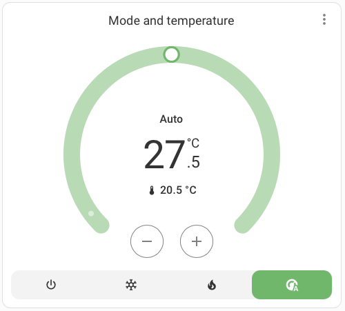 Climate Entity
Then there are the main settings: switches for silent mode, silent mode schedule, and power on/off schedule. The silent mode and schedule switches aren’t behaving quite right yet—toggling the silent schedule one also triggers the current silent mode. I suspect I’m missing a register or there’s a bug in my code.
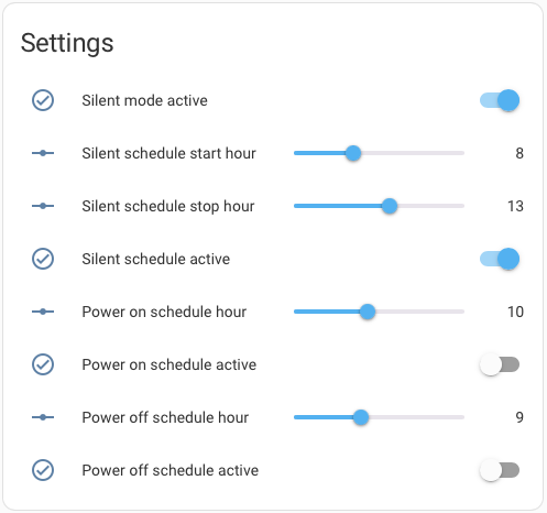 Settings Entities
The sensors are the real win. I’ve got the main ones working, like water inlet temperature, which feeds into the climate entity. There are more sensors I could add, and I plan to dig into the registers to expose them all.
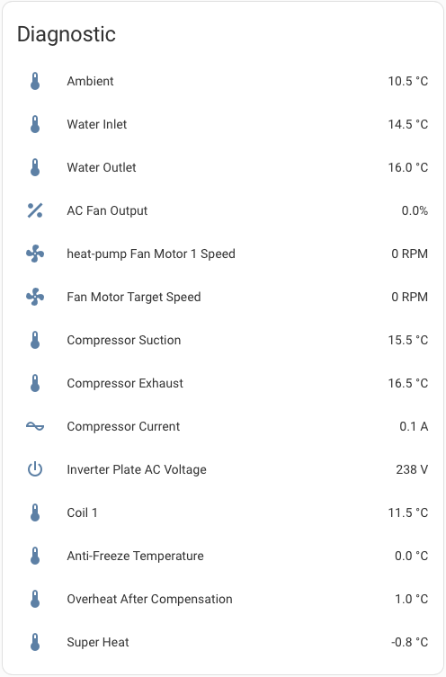 Diagnostic Entities
Wrapping It Up
This project was a blast to work on, and I’m thrilled to see my heat pump finally talking to HomeAssistant. It’s not perfect yet but it’s a solid start. I hope this guide helps anyone else with a Hayward (or similar) heat pump get their setup running. If you give it a shot, let me know how it goes! I’d love to hear feedback or ideas for improving the hayward component.
If you have a device with modbus connection and you’d like to dump the messages first, load only the modified modbus component and set it’s logging to VERY_VERBOSE. You will get a full dump of all messages seen on the Modbus connection, but nothing will be sent.
I will continue working on this component, adding more functionality. At the same time, I’ll be looking for a way to reduce the gap between the upstream version of modbus and my changes. If you have any useful information that could help in this direction, please do share.